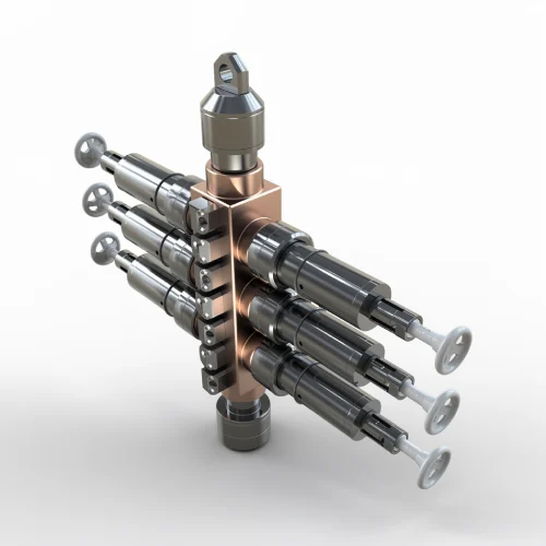
Engineered for reliable well control during critical wireline and slickline operations. Our complete pressure control lineup ensures safe tool deployment and retrieval under pressure, protecting personnel and maintaining well integrity in demanding field conditions.
Four essential components for safe and efficient well intervention operations. Click on any product to view complete specifications.
Dependable well control for slickline and wireline operations with precision-machined components.
Creates dynamic seal around moving line for safe operations under pressure.
Allows tool deployment under pressure without releasing wellbore fluids or gases.
High-pressure flow control for rapid well control and pressure management.
Select a product to view complete technical specifications, features, and applications.
Blowout Preventer
Control Head
Pressure Containment
Flow Control
Wireline Valves (Blowout Preventers) are engineered to deliver dependable well control during slickline and wireline operations. Built from precision-machined, high-quality materials, our valves are designed for consistent performance, easy servicing, and long operational life under demanding conditions.
Single, dual, or triple body designs for varying safety requirements
Available in 5,000 PSI and 10,000 PSI working pressures
Hydraulic actuators standard, manual available on request
Quick redress with readily available service kits
| Single Wireline Valve | Compact and cost-effective for low to medium-pressure wells with single sealing barrier |
|---|---|
| Dual Wireline Valve | Enhanced safety with two independent rams for high-pressure operations and critical interventions |
| Triple Wireline Valve | Maximum safety and redundancy with three sets of rams for the most demanding applications |
| Available Sizes | 3", 4 1/16", and 5 1/8" |
|---|---|
| Pressure Rating | 5,000 PSI and 10,000 PSI |
| Body Design | Single, Dual, and Triple |
| Configurations | Manual and Hydraulic |
| Connections | B7/B09/B17/O10/O07 |
| Quality System | ISO-certified manufacturing |
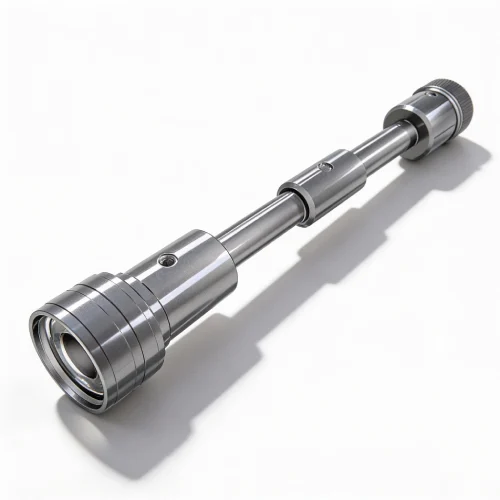
The Grease Injection Control Head (GICH) is the primary well control barrier, providing a seal around moving wireline or e-line during well interventions. Positioned at the uppermost point of the pressure control equipment string, it maintains well pressure while allowing continuous line movement.
The GICH pumps high-viscosity grease into close-tolerance flow tubes at a pressure above well pressure. The grease fills the annulus between the tube I.D. and the line O.D., creating a liquid seal that's maintained as the line moves through the control head during operations.
Handles maximum working pressures up to 15,000 PSI
Maintains grease seal around static or dynamic wireline
Prevents wellbore fluids and gases from escaping
Simple maintenance with readily available parts
| Assembly Number | 13-106-G-005-A0 |
|---|---|
| Max Working Pressure | Up to 15,000 PSI |
| Upper Thread Connection | 4.75" - 4 Stub Acme |
| Lower Thread Connection | 4.75" - 4 Stub Acme |
| Flow Tube Options | Solid or concentric, matched to line size |
| Sub-Assemblies | Combination stuffing box, line wiper, flow tube assembly |
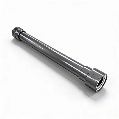
The Lubricator is designed to allow tools and instruments to be run into and out of a well under pressure without releasing wellbore fluids or gases. Made up of threaded tubing sections with hand unions, lubricators are essential for maintaining well control during tool deployment and retrieval operations.
Prevents release of hazardous wellbore fluids and gases
8 or 10 foot sections with hand union connections
Standard 2.875" and 3.5" OD, available up to 7" OD
NACE and sour service specifications available
| Lubricator Joints | Sections of tubing material threaded on both ends to accept hand unions |
|---|---|
| Standard Lengths | 8 foot or 10 foot sections |
| Standard OD Sizes | 2.875" and 3.50" (on slickline service units) |
| Available OD Sizes | Up to 7" outside diameter |
| Sour Service | Machined from NACE spec stock material |
| Connection Options | Machined hand unions or sealed premium thread connections |
| Assembly Number | 13-01-L-300-A0 |
|---|---|
| Upper Thread Connection | 4.75" – 4 ACME |
| Lower Thread Connection | 4.75" – 4 ACME |
| Optional Bleed Sub | Ported .50" NPT sub between tube and bottom hand union |
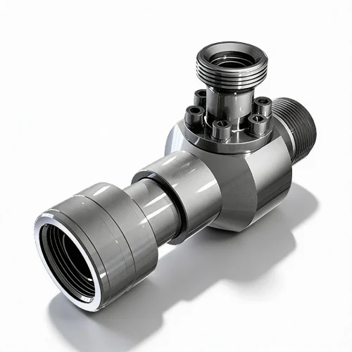
The Pump-In Sub, also known as a High Pressure Flow Tee, provides the ability to either pump into or bleed off wellbore pressure under high pressure conditions. Incorporating a 2-inch high-pressure quarter-turn ball valve, it enables rapid well control and efficient pressure management during critical operations.
2" quarter-turn ball valve for quick well control response
Efficient pumping or bleeding of wellbore pressure
6K Guiberson style union for ease of use and pressure capability
Multiple crossover adapters available
| Assembly Number | 13-06-FS-300-A0 |
|---|---|
| Upper Thread Connection | 4.75" – 4 ACME |
| Lower Thread Connection | 4.75" – 4 ACME |
| Maximum OD | 6.68" |
| Ball Valve Size | 2" high-pressure quarter-turn |
| Union Style | 6K Guiberson (standard), additional options available |
| Flow Sub Body | Part # 13-06-FS-300-01 |
|---|---|
| Hand Nut | Part # 13-06-HUN-300-01 |
| Bottom Union | Part # 13-06-HUM-300-01 |
| X-Over to Nutron Valve | Part # 13-01-CO-300-02 |
| X-Over to Guiberson | Part # 13-01-CO-300-03 |
The Pump-In Sub's larger bore design combined with the quarter-turn ball valve provides operators with both rapid shut-off capability and efficient fluid transfer rates. This dual functionality makes it an essential component for maintaining operational safety while optimizing pressure management efficiency.
Understanding the role and capabilities of each pressure control component helps ensure safe and efficient well intervention operations.
| Component | Wireline Valves | Grease Head | Lubricator | Pump-In Sub |
|---|---|---|---|---|
| Primary Function | Pressure isolation | Dynamic sealing | Containment | Flow control |
| Position in Stack | Below lubricator | Top of stack | Middle section | Variable |
| Max Pressure | 10,000 PSI | 15,000 PSI | Varies by size | High pressure |
| Configurations | Single/Dual/Triple | Standard | Modular sections | Standard |
| Key Benefit | Redundant safety | Moving line seal | Pressure barrier | Rapid control |
A complete pressure control stack for wireline operations typically consists of components assembled in a specific order to ensure maximum safety and operational efficiency:
Single Wireline Valve: Ideal for low to medium-pressure wells (typically under 3,000 PSI) where a single sealing barrier provides adequate safety. Cost-effective solution for routine interventions with lower risk profiles.
Dual Wireline Valve: Recommended for high-pressure operations (3,000-7,000 PSI) and critical well interventions. Two independent rams provide redundancy and enhanced safety, essential for deep wells and offshore drilling operations.
Triple Wireline Valve: Maximum safety configuration for extreme high-pressure wells (7,000+ PSI), sour gas environments, or operations with severe consequences of failure. Three sets of rams offer triple redundancy for the most demanding applications.
Proper grease head operation requires maintaining grease injection pressure above well pressure at all times during line movement. Monitor grease consumption rates and adjust pump pressure as needed. Excessive grease usage may indicate flow tube wear or improper line size matching.
Lubricator length must accommodate the longest tool string plus a safety margin (typically 3-5 feet). For standard slickline operations, calculate: (Longest Tool Length) + (Safety Margin) = Total Lubricator Length. Use 8-foot or 10-foot sections to build the required total length.
Wireline valves should be redressed between jobs or after every 30 days of continuous use. Service kits include rams, seals, and wear components. Inspect ram faces for scoring or wear, replace seals showing any deterioration, and pressure test to working pressure after redress.
Flow tubes require periodic replacement based on line wear patterns. Solid flow tubes typically last longer than concentric designs but may require more frequent grease pumping. Inspect tubes for internal scoring during routine maintenance intervals.
Always maintain at least two independent barriers between wellbore pressure and atmosphere. The grease head serves as the primary barrier during line movement, while wireline valves provide secondary and tertiary barriers. Never rely on a single barrier for well control.
If grease head seal fails (indicated by fluid/gas escape around line), immediately stop line movement and close the uppermost wireline valve. Do not attempt to pull tools through a closed valve. Relieve well pressure above the closed valve before troubleshooting the grease head failure.
Typical onshore vertical well setups use 3" or 4 1/16" equipment with dual wireline valves for wells above 3,000 PSI. Single valve configurations are common in mature, low-pressure fields where wellhead pressures are below 1,500 PSI.
Offshore operations typically mandate triple wireline valve configurations regardless of wellhead pressure due to the severe consequences of well control incidents. 5 1/8" equipment is common for larger bore completions and subsea trees with significant back-pressure.
Unconventional wells with high-volume hydraulic fracturing often experience high wellhead pressures during flowback and production. Dual or triple valve configurations rated for 10,000 PSI are standard, with 4 1/16" or 5 1/8" equipment to accommodate larger tool strings and plug setting equipment.
Our technical specialists can help you configure the right pressure control equipment for your specific well conditions and operational requirements. From equipment selection to stack configuration guidance, we're here to support safe and efficient operations.